Sensing for Science Level 2
Introducing Sensors
A sensor is a device that takes a input from the environment and converts it into
data for us to interpret. Sensors can be complex (dissolved oxygen) or simple (temperature
sensor). When working with sensor on a Arduino board, most sensors will be setup the
same way. We will explore two sensors in this level that will translate to more complex
sensors.
All sensors will need to be connected to an input pin on our Arduino board. These
inputs can be analog (number value ranging 0 to 1023) or digital (on or off). Both
have their advantages and disadvantages, these can be found at:
https://www.softwaretestinghelp.com/analog-vs-digital-signal/
Potentiometers
A potentiometer is a 3-pin variable resistor. The two outside pins are connected to the ground and power. The middle pin is the wiper, this pin’s value changes when you turn the knob, giving us a different voltage value. Potentiometers are sensors, they con-vert the physical rotation of the nob to an electrical input that we can send to the Arduino and get a numerical value for us to in-terpret. The pins on a potentiometer are very delicate so be careful when trying to place them on the breadboard.Potentiometers are used anywhere you see a nob, such as a volume control and speed control. They come in many types and con-figurations.
Circuit 1
Variables
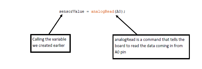
In the first circuit, we will be creating a circuit that will read analog data from the potentiometer and output an analog signal to a LED. Let's get the code written out first. This code will introduce new commands for us to use. Variables—before the void setup we can place lines of code here to create variables. We use variables to give the data in or out a name that we can use for interpreting. There are many variables we can create, we will be using the “int” variable. Typing “int” before setting a variable, tells the code that the variable is an integer. Variable names are case-sensitive. Keep variables simple and easy to recognize what data they are holding. The variables we will be setting are shown below. “sensor value” will be the data coming from our sensor (potentiometer) and “output value” we be our output (LED). We could given pins a variable name as well, but it is not required for this circuit.
Void setup
This circuit we will be using the void setup area to start up our serial monitor.
The serial monitor is a addition in the Arduino IDE that allows us to see data read
by the Arduino board for visual inspection of data, calibrating sensors, and debugging
issues that we may have with the board. As we continue through the different levels
of Sensing for Science we will be using the serial monitor. To start the serial monitor
we will put Serial.begin (9600); This tells the Arduino board to start the serial
monitor when the board is restarted and the serial monitor is opened. Our code for
void setup should look like the code below.
The Loop code
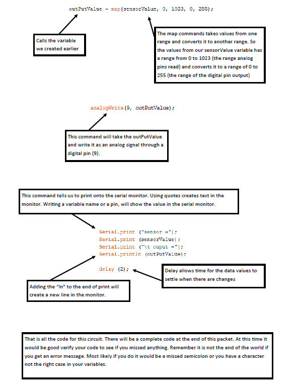
In level one we had pretty simple loop code, but now this area will start getting complex. But we will take it one line at a time and understanding which each command does for us.
Construction
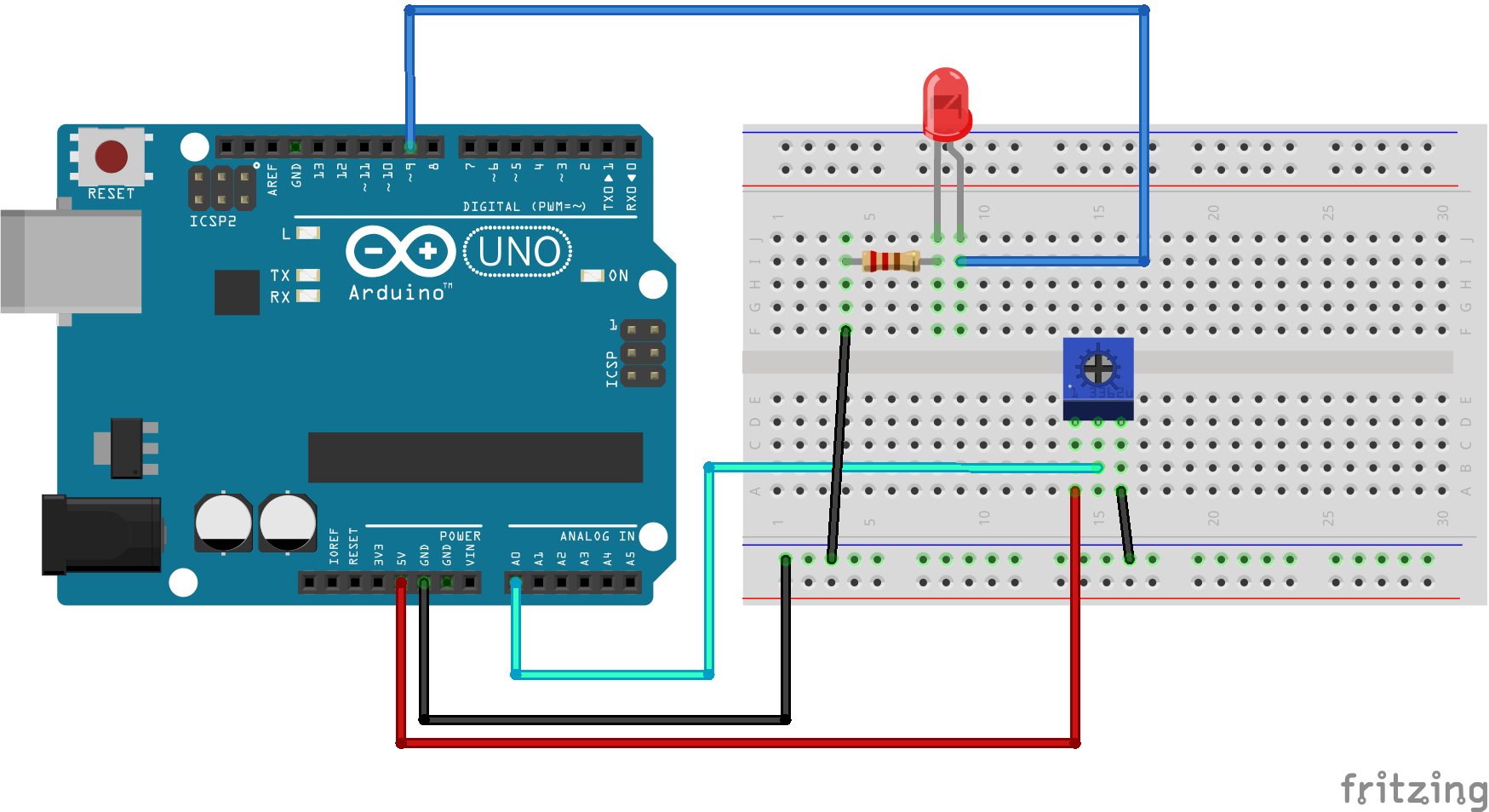
Construct the circuit below using the diagram. When you are finished connect your
board to the USB cable and upload your code from IDE.
Once you have successfully uploaded your code to the Arduino board, keep the USB plugged
in and open the serial monitor in the IDE. The serial monitor is in the upper right
hand corner and looks like a spy glass. A dialog box should open and within a few
seconds you should start seeing you data roll in. When you turn the knob on the potentiometer
you should see the values change on the serial monitor and your LED change in brightness.
We have completed our first sensor circuit. Play around with this one before moving
onto the next circuit for this level.
Circuit 2
Photoresistor
The second circuit we will be creating at this level is a light sensor. We can see this sensor used in automated greenhouses and newer cars that turn on headlights automatically. This sensor will be constructed with two components, a standard resistor, and a photoresistor. A photoresistor is a resistor that changes its resistor value based on the level of ambient light. We are going to use the change in value for our sensor. Photoresistors do not have polarity and be used in either orientation.
The code
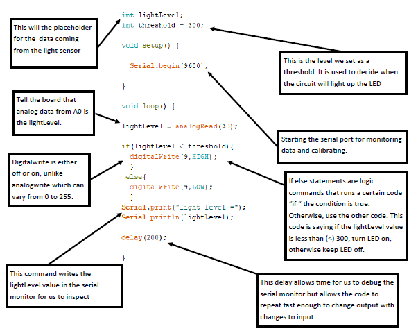
Just like the previous circuit, let’s look at the code we will need for the circuit.
After you have verified your code and fixed any errors, it is time to build the circuit.
Use the diagram in aid of the construction of the circuit.
Construction
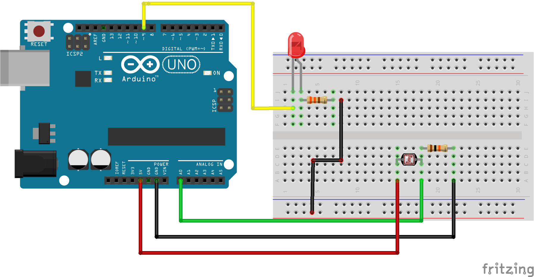
Once you have confirmed you have constructed the circuit correctly, upload the code to the Arduino board. Once it is finished uploading, open the serial monitor and observe the values. Using your finger, cover and uncover the photoresistor and take note of the values. Also, take note of the LED, does it turn off and on? All photoresistors have some variant in them and the threshold might have to be changed for the circuit to work correctly. Play around with the threshold and the delay to see how the circuit reacts. You take components or lines of code from circuit 1 and use them in circuit 2.
Troubleshooting guide:
• My LED doesn’t turn on when I cover the photoresistor -> check connections -> check
serial monitor to see if you are reaching thresholds -> replace LED
• Serial monitor going in a straight line not entering down -> missing a ‘ln’ in the
last line of the serial print.
• Serial monitor showings nothing -> check you port
• Serial monitor values are not changing with the photoresistor -> bad photoresistor
try another one
• Values are not changes when turning the nob of the potentiometer -> pins are not
in the breadboard-> misaligned the pins of the potentiometer->damaged potentiometer
try another one
Sources:
Analog Vs Digital Signal - What Are The Key Differences. (n.d.). www.softwaretestinghelp.com. https://www.softwaretestinghelp.com/analog-vs-digital-signal/
Jost, Danny. “What Is a Sensor?” FierceElectronics, 2019, www.fierceelectronics.com/sensors/what-a-sensor.
SparkFun Inventor’s Kit for Arduino. Vol. 4.0, SparkFun electronics, Inc., 2017.


